SYNOPSIS : Entrusted by NEDO.IGC Research Association has conducted the R & D of an IGCC power system from 1986 to 1996. Nakoso IGCC pilot plant is composed of an air blown gasifier, hot gas cleanup facilities and a gas turbine for low Btu coal gas. After its mechanical completion in March 1991,test operation of the plant was started gasifying a domestic and two Australian coals. Overcoming various difficulties such as the slagging in the gasifier, cumulative operating hours of the gasifier exceeded 4,700 hours, including the continuous operation of 789 hours. Almost all of the results such as the HHV of the product gas,cold gas efficiency of the gasifier, desulfurization and dedusting efficiencies of the gas cleanup facilities and load following capability of the plant, are satisfactory to the target value.
Introduction
As coal is widely distributed throughout the world and its deposits are abundant, development of high efficiency coal utilization
technology is expected to play an important role in Japan for the stable supply of energy resource substituting oil or natural gas.
EspeciallyÅuIntegrated Coal Gasification Combined Cycle Power SystemÅv,which integrates the coal gasification technology and combined
cycle power generation technology (combination of gas turbine and steam turbine),is the most advanced coal utilization technology and
is expected to constitute a major portion of coal fired power plant at the early stage of the 21st century.
1. Implementation of the R&D
After the twice of oil crisis, discussion on the energy policy has been conducted energetically both
in the governmental organization and in private sectors .And the development of advanced thermal power generation technology with high
thermal efficiency and superior environmental compatibility was strongly requested. Further, based on the result of the feasibility study
ofÅuIntegrated Coal Gasification Combined Cycle Power Generation TechnologyÅv(entrusted by New Energy and Industrial Technology Development
Organization or NEDO to Central Research Institute of Electric Power Industry or CRIEPI and conducted from 1983 to 1985) ,MITI related
committee had a discussion on this technology and targets for technical development of the pilot plant were determined. Meanwhile, electric
utility companies had conducted a few years of investigation on coal gasification, organizing a subcommittee in
the R&D division of the Federation of Electric Power Companies in 1980.
Based on the result of the investigation, an IGCC system integrating entrained flow gasifier, hot gas cleanup facility and 1,300Åé
class gas turbine for low Btu gas was adopted and unit size of 200t/d coal consumption ( corresponding to approximately 1/10 of the next
step 250MW class demonstration plant which has the target of 43% net thermal efficiency) was also determined.
Thus,ÅuEngineering Research Association for Integrated Coal Gasification Combined Cycle Power Systems (current chairman : Shige-etsu
Miyahara)Åv,comprising 11 entities ( 9 electric power companies, EPDC and CRIEPI) was established in 1986 and, financially supported by
MITI and entrusted by NEDO , research and development of an IGCC system with 200t/d entrained flow pilot plant (referred to as PP, hereafter)
in the premises of Joban Joint Power Co.'s Nakoso Power Station was initiated in 1986.
2. Outline of the Nakoso pilot plant
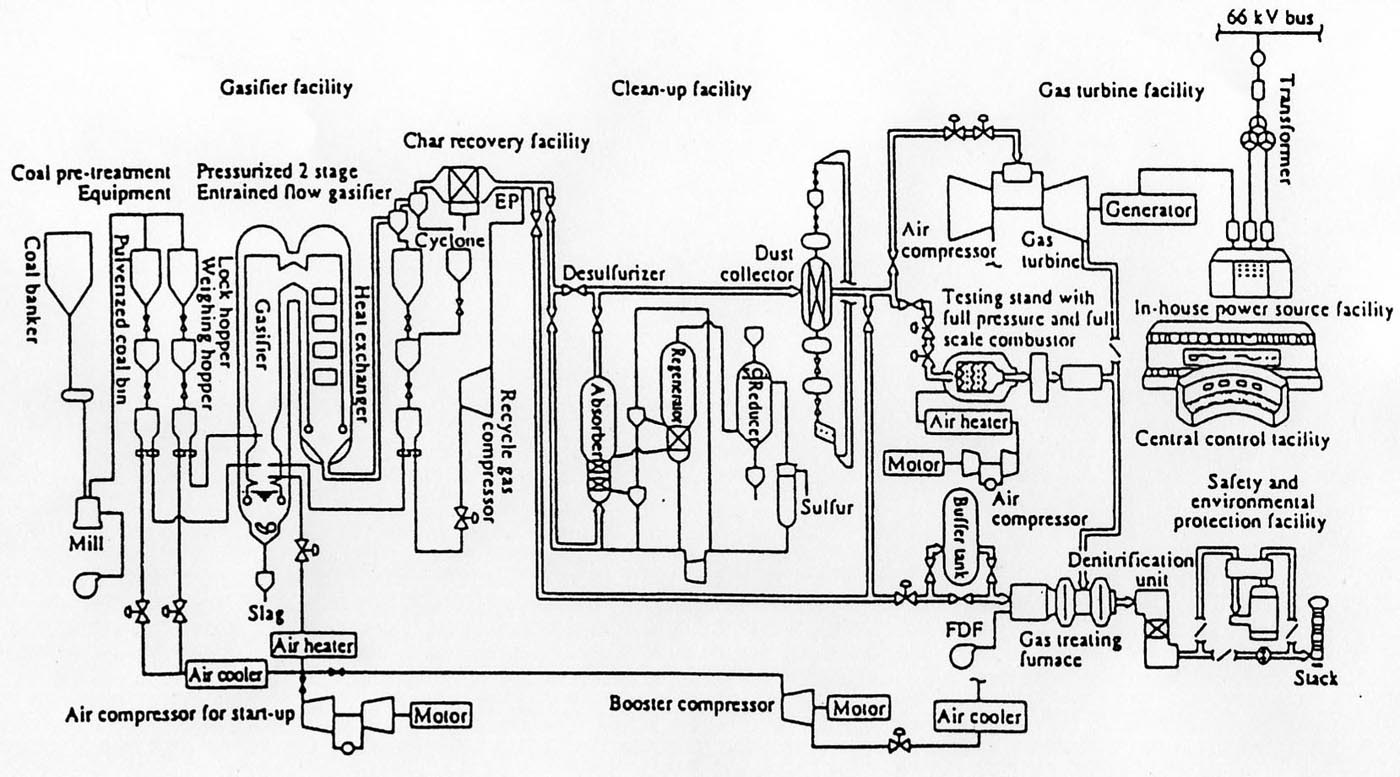
A schematic flow diagram of the Nakoso pilot plant is shown in Fig.1.Main target of this plant is the R&D of an IGCC system composed of an
air blown, pressurized two staged entrained flow gasifier, hot gas clean-up facility and low Btu gas fired gas turbine. And this plant is
aiming at achieving higher thermal efficiency than the similar plants in the world, employing unprecedented unique system.
2.1 Gasifier
As this pressurized two staged entrained flow gasifier uses air for gasifying agent, installation of large air separation unit, which is
indispensable in case of oxygen blown systems, can be avoided.
Coal consumption is 200t/d and gasifier pressure is 27ata. Main component of the product gas is CO and HÇQwith the heating value of around 1,000kcal/mÇRN.
Char in the product gas is recovered and recirculated to the combustor chamber of the gasifier. Ash in the coal pours into the bottom of the gasifier
through slag tap as molten slag. And contacting with water at the bottom of the gasifier, it is quenched and granulated to form glasslike pellets .It is
then discharged out of the gasifier.
2.2Å@Gas cleanup facility
As the gas cleanup facility is composed of unprecedented hot desulfurization and dedusting units ,product gas is supplied to gas turbine at
about 400Åé,resulting in higher thermal efficiency compared with the system employing wet gas cleanup facility. Desulfurization facility is composed
of desulfurizer and regeneration system(regenerator, reductor etc.). FeÇQOÇR is used as sulfur sorbent and sulfur in the product gas reacts with the
sorbent at the fluidizedbed, forming FeS. FeS is then reacted with air at the regenerator to form FeÇQOÇR(for reuse) again .SOÇQin the exhaust gas from
the regenerator is recovered as elemental sulfur by reacting with anthracite at the SOÇQreductor.
Granular filter having 4 layers( 2 layersÅ~2 units) in the vessel is used as dedustor. Synthetic mulite granules is adopted as filter medium and
the granules capture dust in the product gas by moving slowly downward in the filter panel. Dust is then separated by vibrating sieve outside of the
system and the synthetic mulite granules are reused by recirculation.
Although not shown in Fig.1,20t/d equivalent fixed bed type desulfurization / dedusting unit and 4t/d equivalent moving bed type desulfurization / dedusting
unit are installed in Nakoso pilot plant in addition to the fluidized bed desulfurizer / granular filter type dedustor.ÇQÅj
Å@Å@ And the tests were conducted jointly by the manufacturers and IGC Association.
2.3 Gas turbine
The gas turbine was developed aiming at burning low calorie gas of around 1,000 kcal/m3N (approximately 1/10 of LNG ) stably maintaining the
same level of combustor outlet temperature with GT for LNG. This gas turbine is a simple cycle type having six conbustors of 1,260Åé conbustor outlet
temperature and the generator output is 12.5 MW.
A unique constitution of this power system is that air compressor, which is directly connected to the gas turbine, is equipped with air extraction
device in order to convey air to the gasifier as gasifying agent. Further, test stand for a full pressure and full scale combustor, one can of combustor for demonstration plant scale gas turbine(175MW),is
installed in order to conduct tests on stable combustion, high cooling efficiency, NOÇw emission level, etc.
2.4 Steam turbine
Steam turbine is omitted in the Nakoso pilot plant, as it is the state of the art technology and there is almost no R & D items in the system.
2.5 Safety and environmental facilities
Flammable coal gas treating furnace (incinerator),flue gas denitrification (SCR) unit and wet flue gas desulfurization (FGD) are installed to
treat flue gas prior to entering the stack, considering various operation modes such as gasifier alone operation, gasifier+gas cleanup operation,
gasifier+gas cleanup+gas turbine operation etc.
3. Historical overview of the R&D
3.1 R&D schedule
Outline of the R&D schedule is shown in Fig.2. Adjustment operation of the Nakoso pilot plant was started in March 3,1991 by igniting the oil burner.
In June 1991 first coal gas was generated from Taiheiyo coal and in February 1992 product gas was introduced to the gas cleanup facility. In July 1992,
power was successfully generated for the first time by the IGCC system employing air blown entrained flow gasifier and hot gas cleanup system.
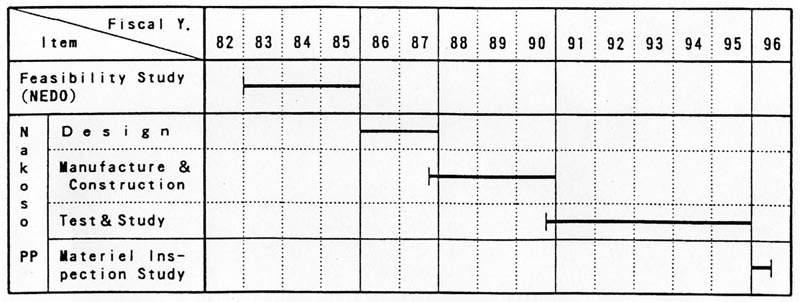

Afterward, twice of plant modification was conducted to solve the slagging problem of the gasifier. From March 3 to April 4,1995,long term reliability
evaluation test using Moura coal (see Table 2) was conducted,achieving 789 hours ( 33days) of continuous operation.
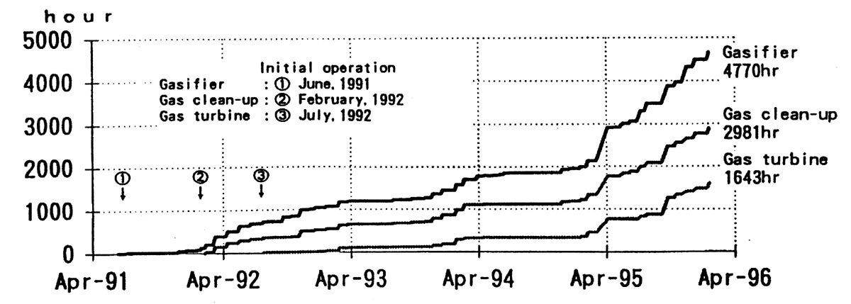
Cumulative operation hours of each facilities during 5 years from June 1991(first Btu) to February 1996(final run) are shown in Table 1. Profile of
cumulative operation hour is shown in Fig.3.
3.2 Troubles and the countermeasures
During the test operation of the Nakoso pilot plant, unexpected troubles occurred from time to time. The troubles may be attributed to the following
factors:
ÅZÅ@Coal feed system, gasifier (reaction zone),gas cleanup system, etc. are under high pressure of 26ata.
ÅZ Valves and pipes in pulverized coal systems and char recovery system,and compressor for char transportation must treat fine powdery materials.
ÅZ Ammonia in the raw product gas brings about unfavourable effect on the sulfur regeneration system.
ÅZ Redundancy of the plant is minimized ,as this is the R & D facility.
Major troubles caused by the above mentioned causes are described below.
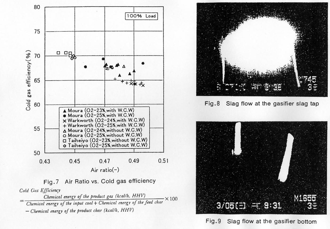
(1) Slagging of the gasifier and its solution
Accompanied by the elongation of the gasifier operation hours and the increase of gasifier load, slag deposition at the reductor section of
the gasifier became evident as shown in Fig.4,forcing the gasifier to shut down during operation. As a countermeasure for this trouble, low temperature
water cooled panels were installed on the gasifier during the plant outage from the middle of April to towards the end of July 1993. However, slagging
trouble was not completely solved. Then, investigations to clarify the slagging mechanism had been conducted using CRIEPI's 2t/d pressurized gasifier,
MHI's 8 t/d atmospheric pressure gasifier and cold model, etc.
Outline of the slagging mechanism is described below in reference to Fig.4.
Pulverized coal is injected into the gasifier through 2 ports, namely combustor chamber and reductor section. At the combustor chamber, pulverized
coal and char (unburned carbon) burn producing over 1,500Åé of high temperature gas which then go upward to the reductor section and gasify pulverized
coal there. Simultaneously, in the combustor chamber, molten coal ash at the high temperature is conveyed to the wall and upward there by the swirling
force caused by the tangential burner angle and the captured slag then flows down. When the swirling force is too strong, part of the molten slag is
pushed upward of the combustor chamber. And in case of high gas velocity (high dynamic pressure) at the " throat section", molten slag is further conveyed
upward which then combines with the pulverized coal injected at the reductor section and, sticking (depositing) on the wall surface in the transition gas
temperature zone, it is calcined there. Thus, following 4 items seems to have strong influence on the slagging phenomena.
á@Å@Upward entrainment of molten slag from the combustor chamber
áA Presence of pulverized coal particle at the reductor
áB Presence of transition temperature zone at the reductor
áC Presence of ready to stick wall surface
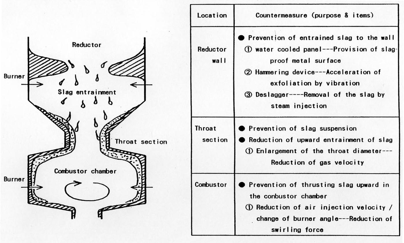
As there is no countermeasures to item áAand áB,various countermeasures to á@ and áC had been investigated. And as shown in Fig.4,various modification
of the gasifier, including the widening the diameter of the gasifier to reduce the gas velocity and dynamic force at the throat section of the gasifier,
was conducted during the period from June to November 1994.After the modification of the gasifier, it become possible to operate continuously without any
deposition of slag. Further, at the last stage of the operation of the Nakoso pilot plant, the plant was operated without any indication of slagging, even
after dismantling the low temperature water cooled panel (and the panel hammering device) which had been installed as a countermeasure of slagging.
Judging from the above mentioned results, the effect of widening the diameter of the throat section was dominant.
(2) Betterment of the coal feed system
Rotating table feeder type equipment is employed for the weighing of pulverized coal. However, disadvantageous phenomenon of sudden over feeding of
coal was found in this feeder, when the quantity of remaining coal in the weighing hopper was small. As a countermeasure, prism like structure was installed
in the hopper to assist smooth falling of coal into the hopper. However, this overfeeding phenomenon did not completely disappear. So, practical countermeasure
of increasing the minimum inventory of pulverized coal in the hopper was adopted. However, it was somewhat difficult to determine the minimum value,
considering the adverse effect of increased coal accepting frequency.
Comparative study of coal feed system should be conducted and the system for the next step "demonstration plant" must be selected after the verification
of the selected system.
Air and the recycle gas (product gas) are used for transporting pulverized coal and char, respectively. As the plugging of the transportation pipe
caused by the moisture content of the recycle gas was experienced from time to time, it is recommended to adopt a transportation system using pressurized nitrogen
in both transportation lines.
(3) Utilization of oxygen as a byproduct of nitrogen production
At the early stage of Nakoso pilot plant operation, heating value of the product gas from the gasifier occasionally fell below 900kcal/mÇRN,
causing unstability of combustion and flame out of gas turbine.
At the latter part of test period, oxygen equivalent to the amount produced as a byproduct of nitrogen production was added. Heating value of the
product gas was then raised by 100-150kcal/mÇRN and it was maintained above 1,000kcal/mÇRN.
In the demonstration plant, nitrogen will be used for transporting coal and char and the oxygen produced as a byproduct of nitrogen production will
also be utilized to enrich air.
(4) Improvement of sulfur recovery system
NHÇR,produced by the decomposition of nitrogen compound in coal and HCl produced by hydrolysis of chloride such as NaCl, are present in the product gas.
Entering the secondary system of gas cleanup (regeneration - SOÇQÅ@reduction) ,they deposit at the inlet section of the sulfur condenser of 300-350Åé
temperature zone forming ammonium chloride (NHÇSCl),which then causes plugging of the sulfur condenser.
By recirculating high purity liquid sulfur, surface of the condenser tubes were coated by sulfur and the period till the plugging of the tube was
markedly extended. However, washing the gas by water would be necessary as a final countermeasure.
Further, in the demonstration plant, recovery of sulfur as gypsum would be preferable to the recovery as elemental sulfur, considering the marketability
of the byproduct (surplus sulfur is in the market because of decrease of sulfur content in gas oil).
4.Results of operation and tests
4.1 Gasifier
Test operation of the pilot plant was started immediately after the mechanical completion of the plant at the end of February 1991. And the first
coal gas was generated in June of that year.
Although various difficulties such as the plugging of the slag hole and slagging of the diffuser /reductor section of the gasifier were encountered
during test operation, they were perfectly solved by modifying the profile of the gasifier. Tests on three coals(domestic Taiheiyo coal, Australian Moura
and Warkworth coals) were energetically conducted in 1995 and satisfactory operating data were obtained. By the way, in order to secure stable combustion
of the product gas at gas turbine, small amount of oxygen was added in the secondary air of the gasifier and in the case of Australian coal
powdery limestone was added in the coal as fluxing agent.
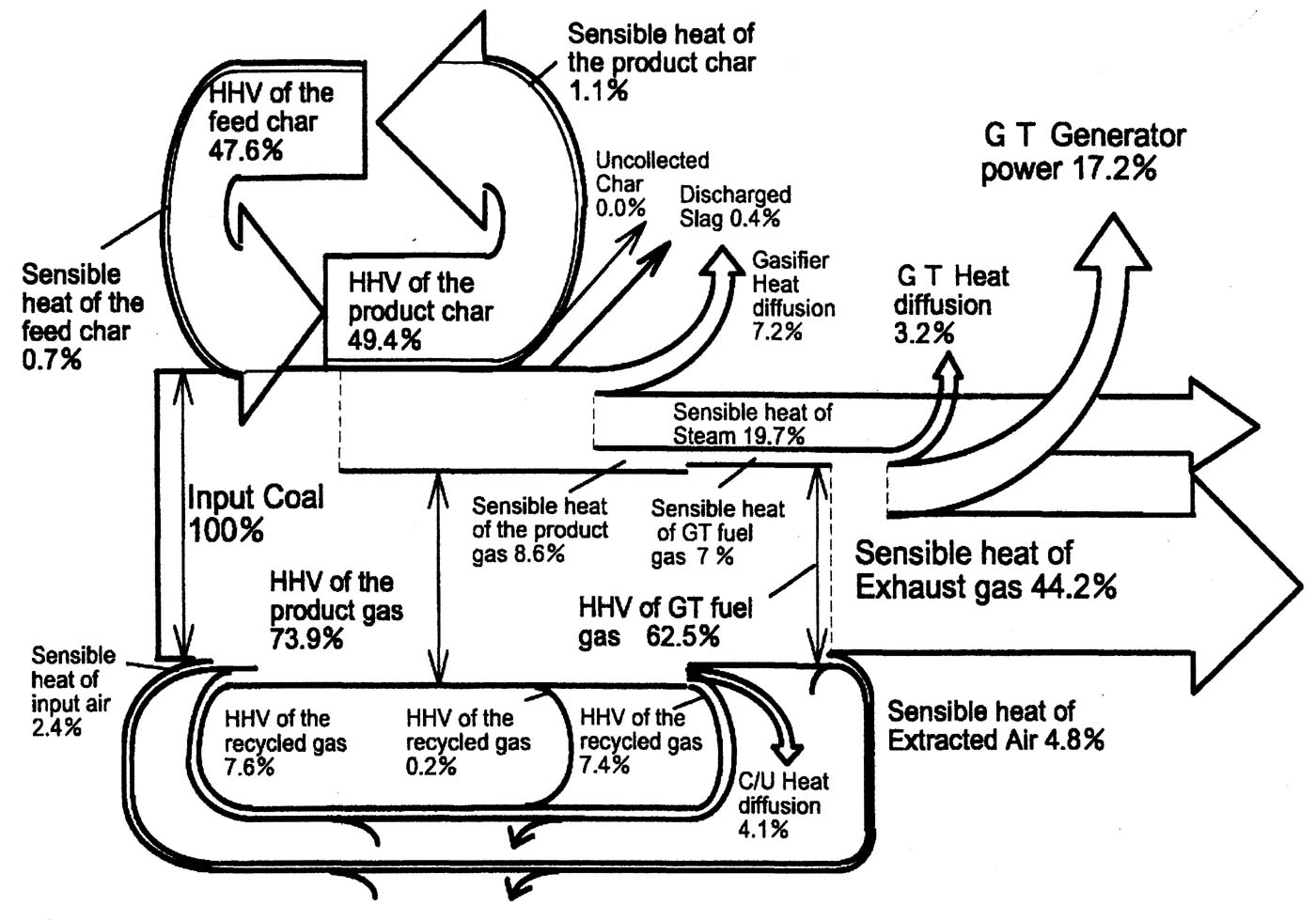
(1) Heat flow
Plant performance tests were conducted on three coals and data were obtained at the rated capacity and partial loads. Example of the heat flow at
the gasification of Moura coal is shown in Fig.5.
(2) Carbon conversion efficiency
Carbon conversion efficiency(amount of carbon in the product gas flow /amount of carbon in the input coal flow) was over 99%,exceeding the target
value (98%<). Residual unburned carbon in the discharged gasifier was found to be less than 0.1wt%.
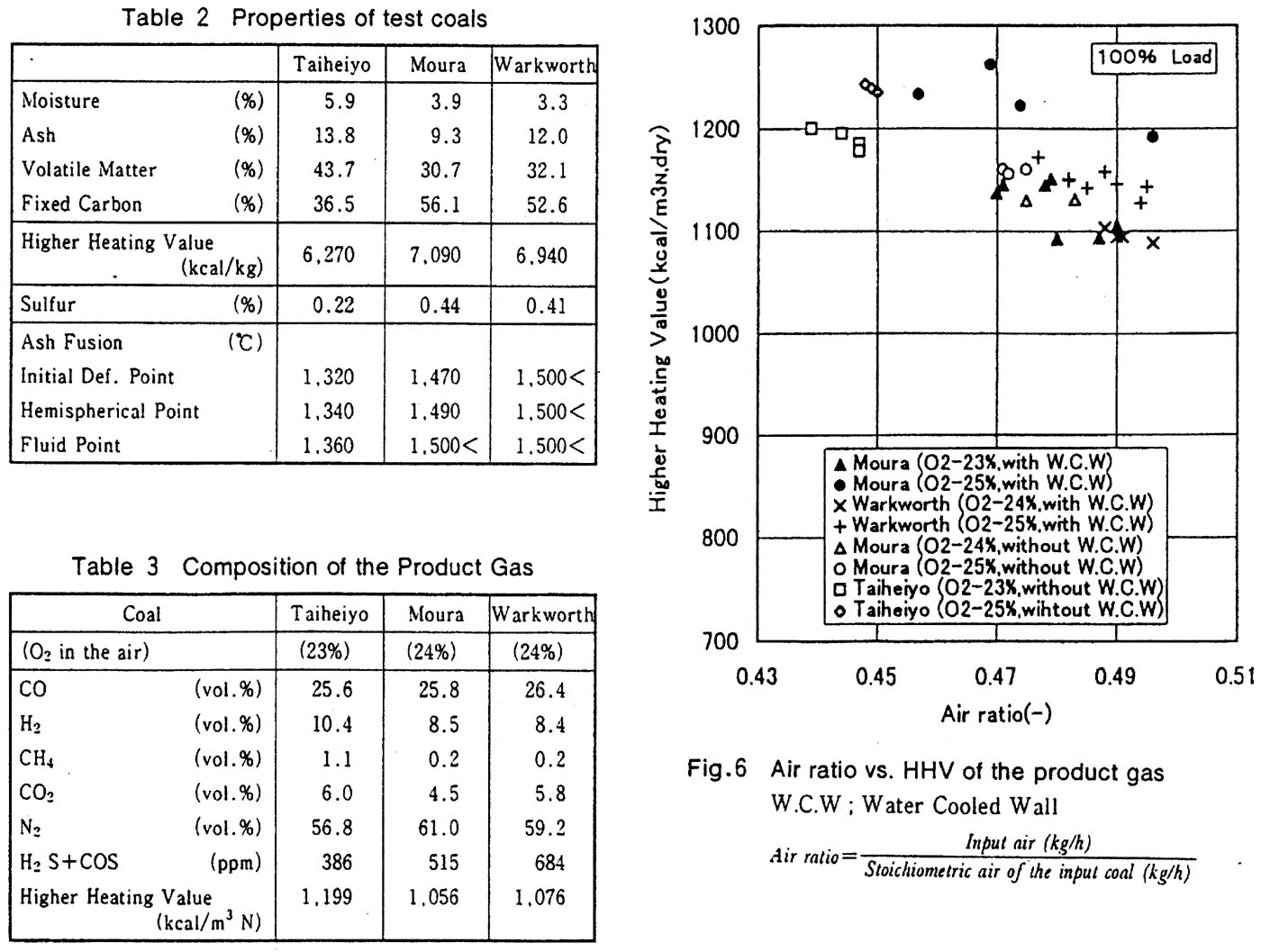
(3) Properties of test coals and the composition and heating value of the product gas
Properties of test coals and composition of theÅ@product gas are shown in Table 2 and Table 3, respectively.
Inflammable components of the product gas are CO,HÇQ and small amount of methane.
Relationship between air ratio and heating value of the product gas from Taiheiyo coal, Moura coal and Warkworth coal is shown in Fig.6.
Data with oxygen concentration of 23-25% ( in the input air) are shown in this figure. In addition, data with and without low temperature cooling
panel (provided at the reductor section to prevent ash deposition) are also shown. In any case, heating value of the product gas increased in
accordance with the decrease of air ratio. At the same air ratio, the higher the oxygen concentration in the input air, the higher the heating value
of the product gas. Heating value of the product gas with the low temperature cooling panel is generally higher than that without the panel. This
phenomenon might be caused by excess feeding of char than the amount of char produced in the gasifier.
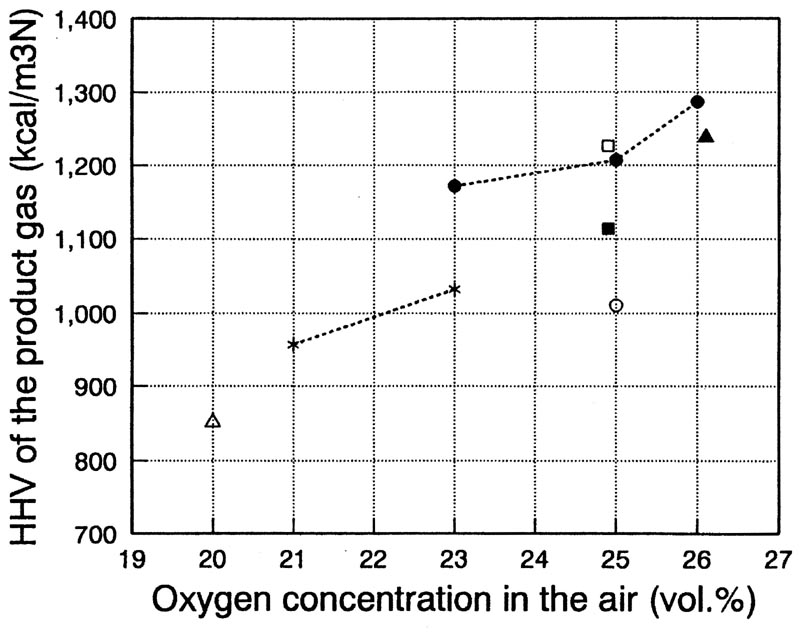
(6) Oxygen concentration in the input air vs. gas heating value
Heating value of the product gas increases by the enrichment of air (gasifying agent) with oxygen. Relationship between oxygen concentration
in the input air and the heating value( HHV) of the product gas is shown in Fig.10.
4.2 Gas clean up facility
During the initial stage of test operation, gas cleanup facility was independently operated using recirculation line. And adjustment operations
were conducted using raw product gas from gasifier since February 1992.
Although some problems such as plugging of sulfur condenser were encountered, solutions were found and the expected performance of
desulfurization and dedusting were confirmed.
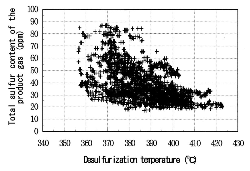
(1) Desulfurization efficiency
As all of the three gas cleanup facilities (main pilot plant, fixed bed type and moving bed type) uses iron oxide as sulfur sorbent,
nearly the same desulfurization efficiency were attained at normal operation (inlet sulfur concentration : 400-1,400ppm). Desulfurization efficiency
sharply drops at the outside of the appropriate temperature range. Therefore target concentration of sulfur (HÇQS+COS) at the desulfurizer outlet
was determined to be 110-100ppm taking into account the temporary temperature drop during the load change. However, at the rated capacity,
total sulfur concentration of 25ppm (close to chemical equilibrium) was expected. As indicated in Fig.11(test result of main pilot plant), around
30ppm of satisfactory sulfur concentration was attained at the temperature above 400 Åé.
4.3 Gas turbine
Gas turbine is designed to start up firing gas oil and the fuel is switched over from oil to coal gas at 25% load. First power generation firing
coal gas was conducted in July 1992.
(1) Stable combustion
At the initial stage of test operation, heating value of the product gas from the gasifier fluctuated considerably and flameout of the gas
turbine occurred from time to time. Based upon these experiences, lower limit of heating value for stable combustion at newly developed combustor
was determined to be arround 800 kcal/mÇRN (LHV, wet ). This figure corresponds to approximately 950 kcal/m3N (HHV, dry),considering the difference
of basis and the dilution by inert gas at the gas cleanup facility.
(2) Operation at high load
After the modification of the gasifier, fluctuation of the heating value of the product gas was minimized and operation of the plant at high load
become possible. And performance of the plant at rated capacity ( output : 12.5MW,thermal efficiency : over 28.2%) was confirmed. Further, metal
temperature of the liner was below the upper limit (850Åé), even when the combustion temperature reached the design value of 1,260Åé.
(3) Load dump test
From the view point of safety, it is requested in Japan that that the maximum speed rise ratio of turbine in case of load dump is under the
limit value(111%) and the turbine can stably continue operation with no load. Load dump tests were conducted at every quarter load. As shown in
Fig.13, satisfactory results (speed rise ratio : 106% at rated load) were obtained. CO concentration of the exhaust gas was around 100ppm after
the load dump.

4.4 Operation and control of the plant
(1) Startup and shutdown of the plant
In case of cold startup it takes nearly 2days for Nakoso IGCC plant, as the prewarming of the gas cleanup facility and pressurizing the system
requires many hours. However it was confirmed that hot restart can be conducted within 8-9 hours.
(2) Load and pressure control of the plant
We have two control objectives in the control system of the plant, namely generator output (main requirement for power plant) and process gas
pressure ( index of stable operation).
Six different control modes can be selected in the integrated load and pressure controller, "plant coordinated mode" being the highest rank mode.
In this "plant coordinated mode", all of the air requirement at the gasifier is supplied by gas turbine air compressor, generator output is
controlled by the gas turbine control valve and process gas pressure is controlled by the adjustment of gasifier input. Test operation of the
integrated load and pressure controller was initiated in January 1994, starting from the tuning of the pressure control loop and tested every
control mode shifting from lower to higher modes.
In the load change test, load change rate was gradually raised from 1%/min to 2,3,5,6,8%/min with above mentioned plant control mode. And finally
10%/min with load change range of 5MW(40%) was tested. Result of the final test is shown in Fig.16. As indicated in this figure, maximum deviation of
the generator output is 1.3% (control target: 5%) and maximum gas pressure deviation is 0.7% ( control target : 1.9%).
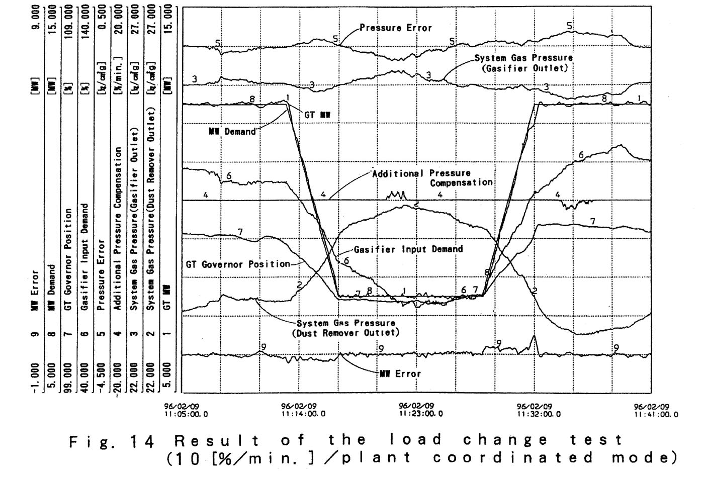
Thus excellent controllability, higher than the target figure, was confirmed and superiority of IGCC power plant over conventional power plant in terms of power system operation was proved.
5. Conceptual design of the demonstration plant
Conceptual design of the next step demonstration plant ( coal consumption : 1,500Å`2,600 t/d )has been conducted since October 1992,reflecting
the operation results of Nakoso pilot plant.
5.1 Thermal efficiency of the demonstration plant
By adopting most advanced high efficiency gas turbine, thermal efficiency of the demonstration plant is estimated to be over 49% in gross
efficiency and 43% in net efficiency, satisfying the target value.
5.2 Power production cost of the demonstration plant
Because of the reasons that the capacity of the demonstration plant is smaller than the recent pulverized coal fired plant (around 1,000MW)
and that it is the first plant ,power production cost of the demonstration plant is supposed to be somewhat higher than that of the conventional
pulverized coal fired plant.
Considering the fact that the Nakoso plant could follow 10%/min of load change easily, the demonstration plant equipped with steam turbine
cycle would be able to follow the load change of 5Å`6%/min. However, as it requires considerably long time for its start and stop, the plant
would be considered as base load power plant or middle load power plant.
5.3 Disposal and utilization of coal ash
Coal ash discharged from the gasifier of Nakoso pilot plant is in the form of glass like pellets and its volume is nearly one half of that
from conventional PC plant. And as it has very small leachability, it is considered as inert waste in case of disposing it for land reclamation.
Further, as a result of investigation of gasifier slag utilization, it was revealed that the slag can be used for a substitute material of clay
in cement industry and can also be used as fine aggregate for concrete.
6.Conclusion
Development of gasifier for IGCC plant was initiated in 1970s and a great progress was made especially in the last few years ,bringing
several IGCC plant in operation.
In the oversea technology, oxygen blown entrained flow gasifier and the state of the art wet gas cleanup facility are adopted. However,
Nakoso PP system(air blown gasifier, hot gas cleaup facility) is attracting keen attention not only in Japan but also from abroad. There are
some items to be cleared such as establishment of scale up technology, verification of scale up technology of the valves and pipes treating
powdery materials. After the investigation of those items, construction and operation of the demonstration plant is strongly looked forward in near future.
Finally, authors wish to extend our deep and sincere appreciation to ANRE, NEDO, Electric Power Companies, CRIEPI ,and related manufacturers
for their instruction and cooperation in preparing this paper.